Tower -
This page tells about important items located at the tower site to make transmission
of the KYFC-


Tower Assembly
Tall television towers are not shipped to the site in one piece. In fact, KYFC-
Dr. Al’s granddaughter, Liane Lewis is shown climbing on one of the sections prior to lifting.
Tower Foundation
The physical construction of a tall tower supported by guy wires begins with a solid
foundation. For the new KYFC-

The anchor holes were all dug by hand with the exception of B-
I will relate one story about the drilled anchor B-
Tower Stacking
September 25, 1978 was an exciting day for KYFC-
A heavy cable from the rooster head will pick up another tower section and the workers will bolt it onto the tower. This continues in a leap frog fashion until they arrive at the point where a guy wire is to be placed. They then attach 3 guy cables spaced by 120 degrees and stretch each out to its respective anchor point. They must do this, otherwise the tower would topple without the guy wires providing the rigidity needed. After the guy wires are attached and tensioned stacking continues until they reach the next point where guy wires need to be attached or until the tower is at its full height.
Of course, weather can impact the ability to work on the tower. I recall being at the tower site one day when a thunderstorm began to roll in. Needless to say, the tower workers will typically evacuate the tower to avoid being on it should it get struck by lightning. I could hear thunder and our crew was scrambling to get off the tower. They were just about off the tower when I noticed the hair on one of the workers standing straight up. That meant there was a lot of static electricity present with a possible lightning strike eminent. Thankfully, all of the crew was able to get off the tower in time.
There was another time that I was working in the transmitter room when a T-
Antenna
The antenna is mounted on top of the tower and transmits the KYFC-


Note that the antenna photo in the picture is the KYFC-
The photo below the sales brochure is an enlargement of the photo. You will notice that there are 3 workers in the air. One is standing on the top plate of the tower to line up the holes for the bolts to attach the antenna pole to the tower. One worker is on the antenna while the third worker is on the gin pole to the top and left of the antenna. This is definitely not work for the faint of heart. It is dangerous work and requires skill in maneuvering massive items weighing thousands of pounds while strapped to a tower with a belt.
After the antenna is set in place the next task for the tower workers is the installation of the transmission line. This line connects between the the transmitter and the antenna. It looks like a 6 inch copper water line. This line carries the high power radio frequency energy on channel 50 from the output of the transmitter to the antenna and broadcasts it to the viewers at home. This line comes in 20 foot sections and must be bolted together. It is then pressurized with dry nitrogen gas to keep moisture from getting into the line. Moisture could cause arcing and resulting in the line burning up. The author has seen this happen and it is not only messy but it is time consuming to replace as well as expensive.

Topping Off
The topping off (i.e. antenna mounted on top of the tower) is a joyous occasion for any TV station. The photo below on the right was taken by same helicopter photographer that did the photo for the antenna manufacture. In the photo the tower crew is close to finishing up the mounting. This photo was taken looking to the northeast. Old Arrowhead stadium can be seen in the upper right corner.
The photo below on the right is a ground view looking up at the completed tower.
The guy wires are visible going out from the tower. You can also see the microwave
antenna in this photo. It is shown as the small dark dot on the left towards the
top of the tower. This antenna receives the audio and video signals from the KYFC-


Above is top view looking down the tower. The tower worker that took this photo is standing on climbing rungs near the top of the antenna. The white rectangle to the right is the roof of the building. The road entering from 56th Street is at the top.
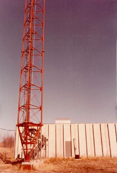
This is a photo of the base of the tower. The tower is 50 feet from the building.
Return to the KYFC-
© 2023 Joe Snelson
Transmitter Building
The building at the transmitter served multiple purposes. First, its primary purpose
was to house the KFYC-
The remainder of this large building was used as storage for scenery, props and other large items used for rallies and other KCYFC activities.
This building, similar to the studio building, was made of pre-
I remember riding with Dr. Al out to the transmitter site one evening. We stopped at Winstead’s along the way and grabbed a hamburger. When we got to the tower site I mapped out a path that needed to be cleared to accommodate Kansas City Power and Light setting poles between a power pole on 56th Street to where the building would be. Dr. Al hopped up on a bulldozer and began to clear the brush and trees for the path. We worked till dark.
Overall KCYFC was able to save significant dollars by doing a lot of the work with staff and volunteers.
Transmitter
Audio and video signals emanating from the studio are transported to the transmitter
site over a private microwave radio link. When the signals arrive at the transmitter
they are sent into a high powered transmitter where they are converted to a radio
frequency on channel 50 and amplified to a very high power using a tube called a
klystron. Then transmitter requires a high voltage, 25,000 Volts, to amplify the
signal. This generates a lot of heat and uses water circulating through the tubes
to keep them cool. The amplified signal is sent up the tower using coax line. This
is not your typical coax cable that connects to your TV set. Due to the high power
involved the coax line is made of 6 inch copper. It looks like a “gi-

The author will relate a story regarding the transmitter. It was mentioned that the Klystron tubes required 25,000 Volts. This was obtained from a large power supply unit that set outside the building. The components in the supply are submerged in mineral oil. I got a call one morning that the station was off the air. I went to the transmitter site and determined that a component inside the supply was defective and needed to be replaced. What hasn’t yet been mentioned is that it was winter time. So, I proceeded to go outside and unbolt the access cover so I could remove the component. I had to reach into the supply with oil up to up to my elbows with a temperature of about 32 degrees Fahrenheit! That was an invigorating experience to say the least.


East side of the building. The large metal door to the right of the trailer allowed trucks to drive inside.
West side of the building. The metal grating going from the tower to the building enters the transmitter room. The 6” copper transmission line carrying the channel 50 signal to the antenna is seen going up near the center of the tower.
Framing the living quarters for the individual providing security at the transmitter site .
I will digress for a moment and share an experience that occurred while stacking. First, I should mention that guy wires are not small. They can range from 3/4” to 1” or more depending on the load they will carry. They are shipped on huge wooden spools and weigh thousands of pounds. Each cable (we had a total of 18) are custom cut to the specific length needed. There is little room for measurement error. Being custom made it can take months to get a cable made and delivered.
I was working at the studio one day when I received a phone call from a tower worker
telling me a set of cables were too short! I immediately got in my car and made a
mad dash to the tower site. When I arrived the crew had stacked about half the tower.
All guy wires were attached to anchor points A-
I then called the tower fabricator, Stainless, Inc., and spoke to their Chief Engineer. He said what we were experiencing had happened before and suggested extension plates be fabricated to attach to the end of the guy cables to make up for the length shortage. My concern was how long it would take to get the extensions fabricated. It would cost a lot of precious time and money if the tower crew had to pull off the job for a week or so. The engineer sent me a drawing of the extension plates he proposed with the dimensions. I was hoping I could find a local fabricator.
Dr. Al was blessed to have another talented person on his Board of Directors. Tom Gaskell had a company that manufactured bolts and rivets. He had the equipment to fabricate the plates and get them galvanized for rust protection. Tom cranked them out within a few days. The plates worked great and we were now back on schedule for tower stacking with only a couple of days delay. When the stacking was completed the antenna was lifted up and mounted on top. Even under ideal conditions stacking is a slow process and can take weeks to stack a tower.

The kick-


The photo above on the left is the front of the Harris BT-
One other interesting item, notice on the rear view the round domes on the stop. This tube was cooled by water. It would boil the water into steam. The steam would be collected in the dome and condensed back into water with a huge coil and fan unit, called a heat exchanger, and sent back to the transmitter for another cooling cycle.
Klystron tubes were not cheap and could cost as much as $50,000! They might last for 3 to 5 years.
Front of the KYFC-
Rear of the Transmitter
Klystron Tube